PROJECTS / WEATHER STATION 1.0
Weather Station 1.0
- STARTED
- 13/06/2020
- BY
- Michael Pope, Danch
- TAGS
- hobby
Weather station
13th June 2020
OVERVIEW
A Wifi External Weather station.
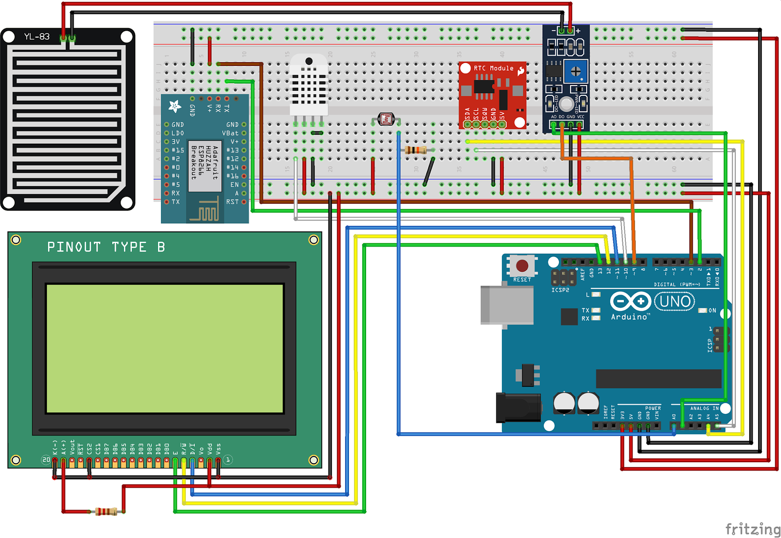
Hardware
What | Model | Price |
Controller | Arduino Uno R3 | 50 |
Screen | Z6502 LCD 128x64 DFRobot | 45 |
WIFI | 19 | |
Rain Sensor | 9 | |
Clock | 6 | |
Light Sensor | LDR + Resistor | 1 |
Temperature/Humidity | DHT22 | 20 |
Pressure sensor | 23 | |
Debug | RS232 TTL -> RS232 to USB Unitek | 20 |
Case | Waterproof jaycar case | 20 |
Power | 5v | 10 |
Total | 223 |
Resources
Michael has;
https://core-electronics.com.au/projects/diy-weather-station-raspberry-pi[a]
Book: Arduino Project Handbook Chapter 13: building a weather station
Looks like a good place to start, has a POT, 2 line LCD & Humidity & Temp sensor
Book: Arduino Workshop
Chap 7: LCD
Chap 14: Wireless data
project #60: Building a remote-monitoring station
In this project he describes exposing temperature and light sensors in a webpage all from the arduino.
https://www.hackster.io/ashshaks/esp8266-temperature-and-humidity-asynchronousweb-server-590d2e
https://core-electronics.com.au/projects/
https://core-electronics.com.au/projects/basic-weather-station
https://core-electronics.com.au/projects/thingspeak-temperature-pressure-logger
https://core-electronics.com.au/projects/rain-gauge-data-logger
GOALS
SPECIFICATIONS
12V SLA battery
Arduino Uno or Mega ( if more ports are needed )
Temperature, Humidity and Barometric Sensor (BME388/680 & DHT11/22)
LCD 128x64
RTC for date/time
Wind Speed Sensor (Magnet)
Daylight Sensor (LDR)
Rain sensor
Rainfall level
Wifi (ESP8266)
3D print enclosure
Phone app (OpenHAB)
Recently ordered Sensors :
Core Electronics :
WiFi Module - ESP8266
DHT11 Temperature and Relative Humidity Sensor Module
Gravity BMP388 Barometric Pressure Sensors
Standards
Coding style
Methods CamelCase eg;
def void GetDHT()Split code into methods instead of having a lot in the loop.
Tools
GIT
Using Git for version control and source code collaboration.
https://rogerdudler.github.io/git-guide/
https://www.freecodecamp.org/news/learn-the-basics-of-git-in-under-10-minutes-da548267cc91/
Example: Linux Command line
Create the git repository
$ mkdir test_git
$ cd test_git
$ git init
Create test.txt file using a text editor adding the following text;
Testing
One
Two
Check status
$ git status
NOTE: At anytime git status will tell you where you what is happening.
Add changes
$ git add test.txt
$ git status
NOTE: Check that the file has gone ‘green’ and into the committed area.
Commit changes & log
$ git commit -am ‘Add a file’
$ git log
Hit ‘q’ to quit the log
Create a branch and checkout that branch
$ git checkout -b dev
Edit the test.txt file again and add ‘Three’ to just after ‘Two’
Commit & log
$ git commit -am ‘Add three to the file’
$ git log
Change back to master
$ git checkout master
Notice that when you look at the contents of test.txt now it doesn’t have ‘Three’ in it as that edit is stored in the ‘dev’ branch.
Edit the test.txt file again and add ‘Four’ to just after ‘Two’
Commit & log
$ git commit -am ‘Add four to the file’
$ git log
Merge dev onto master
$ git merge dev
NOTE: This will create a conflict because we edited the same line in two branches. This is the same thing which happens when you are pulling my changes.
Edit file test.txt and you will see the following;
Testing
One
Two
<<<<<<< HEAD
Four
=======
Three
>>>>>>> dev
HEAD is where you are currently sitting in this case it’s master branch, and dev is what you are merging onto HEAD. Here we can see ‘Four’ is on the master branch and on the same line in ‘dev’ we have ‘Three’. You have to choose the right one and in some situations this might be a mixture of the same line. In programming this can happen.
After editing the file and selecting that we want ‘Three’ not for we should edit the file manually to produce the following;
Testing
One
Two
Three
NOTE: All I’ve done in my editor is delete the unrequired lines and the git conflict lines with <<< and >>> and ==== in them.
Status
$ git status
At this point if you look at status git tells you what you have to do. It’s saying you have to use ‘git add’ to mark resolution, meaning that the file has been fixed from the conflict and is ready to commit.
Add the file to resolve conflict
$ git add test.txt
Commit
$ git commit
NOTE: We don’t add a message to our commit as we are technically still in a merge and the merge will enter a commit message automatically. When doing this command it will load the default editor on your machine. You will see the default git commit message which should be “Merge branch ‘dev’”. Just exit the editor and it will do the commit.
Look at the changes through log
$ git log
NOTE: these commands can be done under Windows also, just some of the system commands like mkdir is different.
GUI tools
https://git-scm.com/download/gui/linux
Program | Opinion | Rating x/5 |
GitKracken | Too complicated, have to purchase to get useful features | 3 |
Gitg | Doesn’t handle new files nicely | 4 |
Git cola | Hard to find log | 2 |
Giggle | Doesn’t initiate git repos, hard to change branches | 2 |
SmartGit | Too complex, costs money | 1 |
Github Desktop | Too many permissions for my liking | 1 |
ungit | AWESOME | 5 |
Ungit
Install
https://github.com/FredrikNoren/ungit
Install
$ apt install nodejs npm git
$ npm install -g ungit
Running
$ mkdir test_git
$ cd test_git
$ ungit
NOTE: This will open a webpage and you use the GUI in there, it’s a web app.
Running
$ cd <weather station>
$ ungit
Jitsi
Video conferencing tool coz of the virus!
URL: https://meet.jit.si/geek
Password: Jean-Luc Picard
Other software of interest
PICsimlab = Design & simulate Arduino circuits
Emacs = Mick’s editor of choice (Does DOS & UNIX modes and compiles arduino)
Check out https://www.spacemacs.org/ if interested in this.
https://fritzing.org/ = Design circuits easily.
Screen to output the console on the terminal
$ screen /dev/ttyACM0 9600
Optional Sensors/Output
We both want to keep the same code on our devices so that we can both benefit from working together. We have slightly different components and those optional components could be switched on/off using the following;
Create a options.h file with the following
#define BMP388 “true”
Import it in your project
#include “options.h”
Do the if statements around the method call
If (BMP388 = “true”){ bmp = getBMP388() }
Possible i2c conflicts with sensors
RTC and BMP388 share i2c and are affecting results.
Possible solution : http://www.learningaboutelectronics.com/Articles/Multiple-I2C-devices-to-an-arduino-microcontroller.php
Datasheet address for BMP388 = 236 or 238 ( 11101100 or 11101110 ) ( seems like 0x77 default or 0x76 is the address )
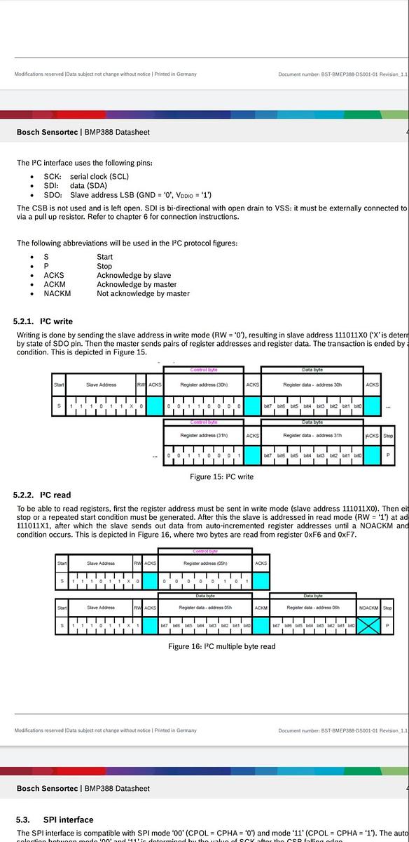
Possible location for RTC
Your DS1307 clock module also has a 23LC32 EEPROM included. The RTCC is at address 0x68, the EEPROM is at address 0x50.
I2C device found at address 0x50  !
I2C device found at address 0x68  !
Powering/Data
Power
Mick is using a 5V 3A brick directly to the GPIO. This is so I can split off some 5V to the RS232 TTL and save some of the cables in the network cable.
Data
Currently using a USB Type-B to Type-A. Problem with this is it doesn’t fit into my (Mick’s) enclosure.
Adding Output
LCD Screen
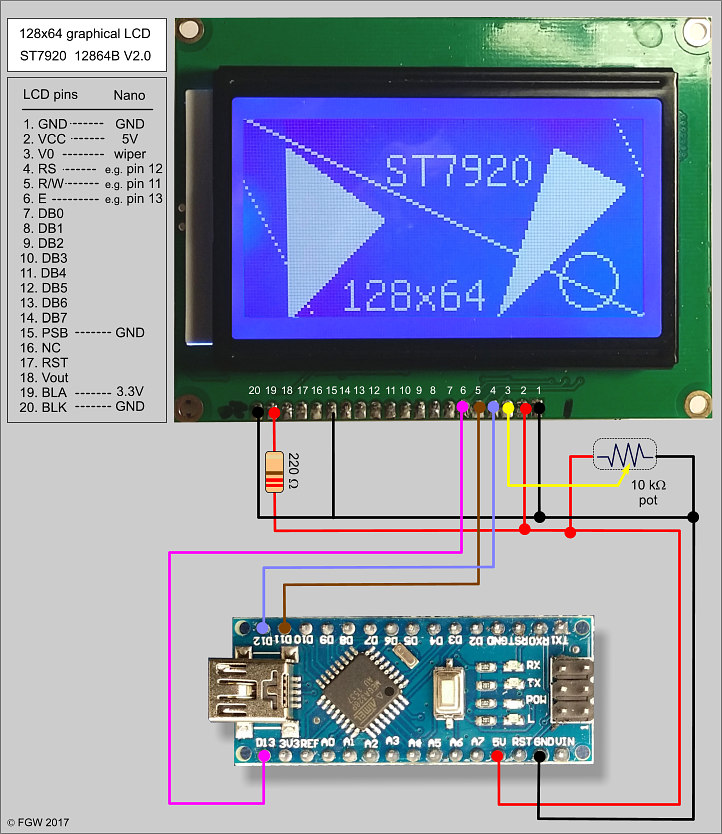
Mick brought Z6502 from Altronics this is a DFrobot board with a nice little attachment.
https://wiki.dfrobot.com/3-wire_Serial_LCD_Module__Arduino_Compatible___SKU_DFR0091_
We went with Method 2 from the above tutorial.
5v power | VCC | red |
Ground | GND | black |
Clock | SCK | green |
Chip Select | CS | blue |
Data | SID | yellow |
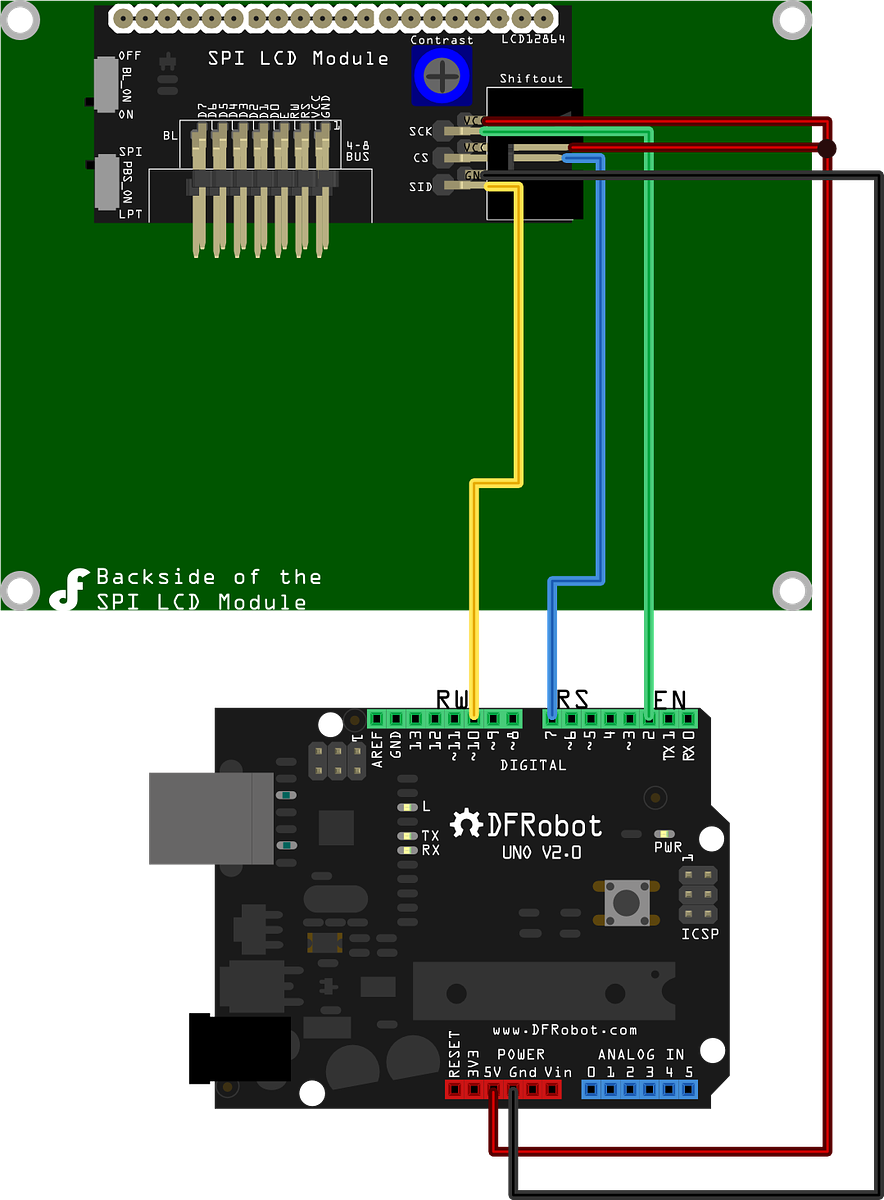
Pinouts For Daniels Model :
UTF-8 characters: https://www.w3schools.com/charsets/ref_html_utf8.asp
Better resource: https://www.utf8icons.com/
https://en.wikibooks.org/wiki/Unicode/List_of_useful_symbols#Physics
HelloWorld LCD Example
Install U8g2 Library
Manage Libraries -> Search U8g2
Download [bad]
https://www.dfrobot.com/image/data/DFR0091/LCD12864RSPI.rar
Install library
$ unrar x LCD12864RSPI.rar
$ mv LCD12864RSPI ~/sketchbook/libraries
NOTE: We had trouble with this library and gave up, moving over the U8g2 library which is easier and better.
Using the LCD_Matrix_HelloWorld example it works with U8g2 library 2.27.6
Other References
https://github.com/olikraus/u8g2/wiki/u8g2optimization
https://github.com/olikraus/u8g2/wiki/setup_tutorial
WIFI (ESP8266)
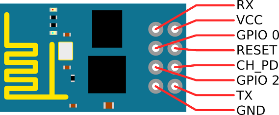
Pins
ESP8266 | Arduino |
VCC | 3.3V |
GND | GND |
CH_PD / EN (pull up resistor optional) | 3.3V |
RX | 2 |
TX | 3 |
3.3v so use separate ground to 5v from arduino.
As we will be shutting down the ESP8266 to save memory it makes sense that the Arduino should make a POST to a backend web service.
Device: https://www.altronics.com.au/p/z6360-esp8266-mini-wifi-breakout-module/
http://zeflo.com/2014/esp8266-weather-display/
Page describing the deep sleep function to put 8266 to sleep to conserve power
-https://randomnerdtutorials.com/esp8266-deep-sleep-with-arduino-ide/
https://hackaday.com/2020/07/02/easy-secure-https-with-an-esp8266/
Mick = https://www.altronics.com.au/p/z6360-esp8266-mini-wifi-breakout-module/
https://www.instructables.com/id/ESP8266-mini-Tutorial/
Basic connection
Ref: esp8266-setup-and-first-wifi-connection
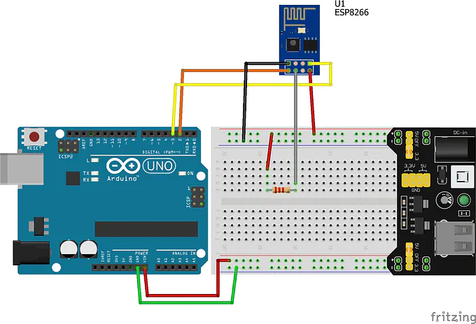
NOTE: We connected the 3.3v from the Arduino directly to the VCC of the ESP8266 and also to the CH_PD pin without a pullup resistor.
Install Adafruit ESP8266 v1.1.0 library
#include <SoftwareSerial.h>
SoftwareSerial ESPserial(2, 3); // RX | TX
void setup() {
Serial.begin(115200); // communication with the host computer
//while (!Serial) { ; }
// Start the software serial for communication with the ESP8266
ESPserial.begin(115200);
Serial.println("");
Serial.println("Remember to to set Both NL & CR in the serial monitor.");
Serial.println("Ready");
Serial.println("");
}
void loop(){
// listen for communication from the ESP8266 and then write it to the serial monitor
if ( ESPserial.available() ) { Serial.write( ESPserial.read() ); }
// listen for user input and send it to the ESP8266
if ( Serial.available() ) { ESPserial.write( Serial.read() ); }
}
Saved as ~/sketchbook/ESP8266_basic
In your serial monitor set Board to 115200 and Both CR & NL
Test with;
AT
Set to 9600 Baud
AT+UART_DEF=9600,8,1,0,0
Now change code from 115200 to 9600 and upload
Setup WIFI into Station mode (other modes are 2=Access Point or 3=Both)
AT+CWMODE=1
List WIFI
AT+CWLAP
Join my WIFI
AT+CWJAP="SSID","password"
It connected!!
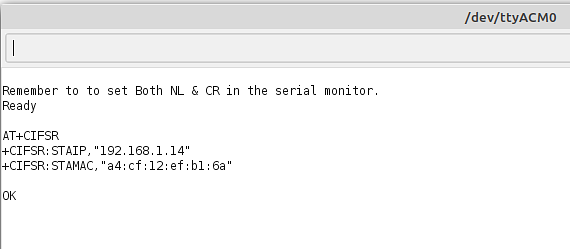
Get IP address
AT+CIFSR
Here it is in my network checking my router and I can also see it.

Webclient thingspeak
https://medium.com/@cgrant/using-the-esp8266-wifi-module-with-arduino-uno-publishing-to-thingspeak-99fc77122e82 - Great example, takes you from AT commands to hooking it up in Adruino code.
Saved in ~/sketchbook/ESP8266_webclient_thingspeak
Create thingspeak account (free)
https://thingspeak.com/login
Sign up and login (remember to click the little checkbox underneath to sign up your personal email).
Setup a channel with one field
Click on API tab and record the Write API & Read API keys
Take note of the ‘Write a Channel feed’
GET https://api.thingspeak.com/update?api_key=<WriteAPI>&field1=<val>
Test in a browser
https://api.thingspeak.com/update?api_key=<WriteAPI>&field1=27
Connect up using the “Basic connection” above and then continue with the following
NOTE: In the tutorial they talk to the ESP8266 directly via the Arduino whilst we are using the ESP8266 on the Arudino. The difference is the code in their example runs on the ESP8266 whilst ours runs on the Arduino.
Connect to ThingSpeak
AT+CIPSTART="TCP","api.thingspeak.com",80
Send a value ‘15’ to our backend
AT+CIPSEND=51
GET /update?api_key=XXXXXXXXXXXXXXXX&field1=27
AT+CIPCLOSE
Review the channel
https://thingspeak.com/channels/1097373/private_show
Other example: http://microcontrollerproject.com/esp8266-arduino-send-data-to-web-server-tutorial-with-example/
Next
Try Sending our results to OpenWeatherMap.org as this is supported by OpenHAB for the frontend interface.
Adafruit_ESP8266 - Broken
File -> Examples -> Adafruit_ESP8266 -> webclient
I put in my credentials and commented out the LED lines and reset lines and it had trouble connecting to the WIFI on the following line;
if(wifi.connectToAP(F(ESP_SSID), F(ESP_PASS))) {Check if we need the reset PIN connected? I did try this but it didn’t seem to help.
Check other examples using the same library
Look around for another ESP8266 library to use.
ESP8266 library - Broken
https://arduino-esp8266.readthedocs.io/en/latest/esp8266wifi/readme.html
Another Examples
http://fab.cba.mit.edu/classes/865.15/people/dan.chen/esp8266/
Storing credentials in secret file
Create a ‘arduino_secrets.h’ file in the same directory as your project with
#define SECRET_SSID ""
#define SECRET_PASS ""
Add the secrets file in your project at the top
#include "arduino_secrets.h"
Use the variables in your code
Web Interface
Use OpenHAB + Serial addon / Weather add-on
Easy image which is ready to go https://ubuntu.com/appliance/openhab
Start with Serial addon
Then migrate to Mysensors;
https://community.openhab.org/t/can-i-connect-arduino-to-openhab/55331/20
https://homeautomation.proboards.com/thread/583/openhab2-arduino-usb-i2c?page=1&scrollTo=4089
Ref: https://github.com/awesome-selfhosted/awesome-selfhosted#internet-of-things-iot
ThingSpeak
My charts: https://thingspeak.com/channels/1097373/private_show
Free for private use, but not as flexible as we would like.
OpenWeatherMap
Open Weather Map is free API and can be used in a lot of different open source services such as OpenHAB.
Follow these instructions: https://openweathermap.org/appid
Weather Station API 3.0 specific information https://openweathermap.org/stations
Pros
Have as many weather stations as you need on a free account.
RESTful interface
Install
Create an account & get your API keys
API keys: https://home.openweathermap.org/api_keys
Register your weather station
Post results
Node-RED solution
This runs on a local server and uses block to create the code for your server.
https://randomnerdtutorials.com/getting-started-with-node-red-on-raspberry-pi/
https://iotdesignpro.com/projects/interface-arduino-with-node-red-to-send-sensor-data-on-webpage
Pros
Easy
Self-hosted
Up and running fast
Graphs
Cons
Limiting
Install
Install Node
Make sure you have node 10.16.x & npm 6.9.x installed
Install Node-RED
npm install -g --unsafe-perm node-red
Install Arduino Node RED requirements
Install Arduino nodes
npm install node-red-node-arduino
Install serial port node
npm install node-red-node-serialport
To install the Dashboard nodes
npm install node-red-dashboard
Run Node-RED
node-red
Load the editor
http://localhost:1880
I followed the tutorial with a few changes
My device setup in Node-RED
Serial Port /dev/ttyACM0
Split input on the character \n
And deliver binary buffers
Arduino code change last print to a println eg;
Serial.println(temp1);
Arduino change DHTPIN to 10
#define DHTPIN 10
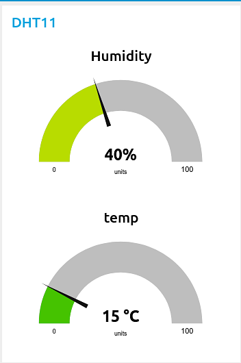
Result
Rails 6.x
Install a Rails 6.x project with a PostgreSQL database
Pros
Powerful
Easy for the size
Extendable
Cons
Learning curve
More moving parts
Adding Sensors
To get working in easiest to hardest order
Sensor pack Mick brought https://www.altronics.com.au/p/z6311-37-in-1-arduino-compatible-sensor-shields-module-kit/
Temperature/Humidity (DHT11/DHT22)
DHT | Arduino |
VCC | 5V |
GND | GND |
Data | 10 |
https://www.circuitbasics.com/how-to-set-up-the-dht11-humidity-sensor-on-an-arduino/
DHT11 (Danch, Mick)
Initial Library used and working :
https://www.circuitbasics.com/how-to-set-up-the-dht11-humidity-sensor-on-an-arduino/
Download DHTlib.zip
Sketch -> include library -> Add from zip
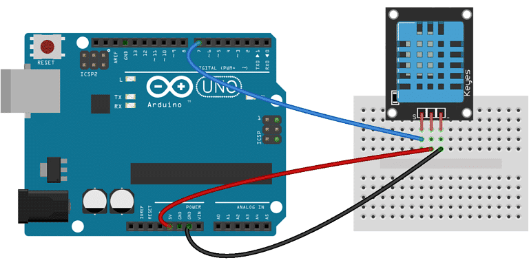
TEMP & BARO (BME388/BME680)
BMP388 | Arduino |
VCC | ? |
GND | GND |
SCL | ? |
SDA | ? |
BME680 (Mick) - https://shop.pimoroni.com/products/bme680-breakout
BMP388 (Danch)
References;
https://create.arduino.cc/projecthub/dragos-iosub/arduino-bme680-gas-and-ths-air-quality-monitor-d58a10
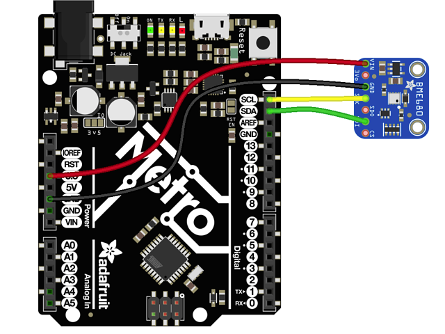
BME680
Install Adafruit BME680 Library from the Library Manager Version: 1.1.1
Tutorial I’m following for BME680 https://learn.adafruit.com/adafruit-bme680-humidity-temperature-barometic-pressure-voc-gas/arduino-wiring-test
Tried this tutorial and got this error: “Could not find a valid BME680 sensor, check wiring!”
Next:
Test BME680 unit on Raspberry PI with the Pimororni python code to make sure the sensor is still working.
Test the BME680 in PICsimlab
Other references
http://www.pibits.net/code/arduino-and-bme680-environmental-sensor-example.php
https://github.com/adafruit/Adafruit_BME680/blob/master/examples/bme680test/bme680test.ino
https://shop.pimoroni.com/products/bme680-breakout
BMP388
BMP388 | Arduino |
VCC | 5v |
GND | GND |
Data | I2c using pins A4 and A5 |
Reference for Daniels BMP388 and 3xx Library
https://learn.adafruit.com/adafruit-bmp388/arduino
20/07/20 - When attempting to compile the program without the bmp ( w/ rtc, 8266, dht, lcd and ldr attached), the value was roughly 28k out of 32k. Including the bmp at its stock oversampling rate of 8x for temp and 4x for pressure it blew out the program size to 35k. I've reduced oversampling to 2x for the time being, but might have to remain there unless we can regain some space.
bmp.setTemperatureOversampling(BMP3_OVERSAMPLING_2X); // 388 Set up
bmp.setPressureOversampling(BMP3_OVERSAMPLING_2X); // 388 Set up
DAYLIGHT SENSOR (LDR)
LDR | Colour | Arduino |
VCC | Red | 5V |
GND | Black | GND |
Data | Yellow | A0 |
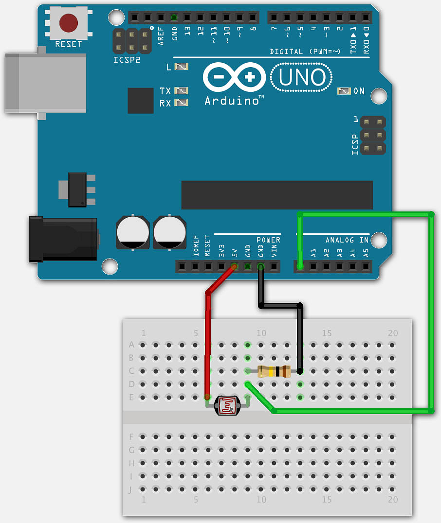
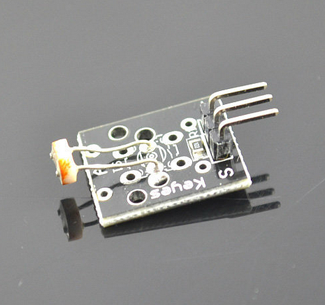
LDR
To capture light levels during day and sunrise and sunset
https://www.tweaking4all.com/hardware/arduino/arduino-light-sensitive-resistor/
Mick noticed that his “fancy” LDR out of the kit doesn’t work. So I’m going old school and putting the LDR & 10k resistor like above.
Readings
Person | Min | Max |
Mick | 35 | 993 |
Danch | ||
Actual | 0 | 1023 |
Weather LDR readings
Situation | Reading |
Night | |
Cloudy | |
Sun |
Real Time Clock (RTC)
RTC | Colour | Arduino |
VCC | red | 5V |
GND | black | GND |
SDA | yellow | A4 |
SCL | green | A5 |
Tiny RTC (Mick)
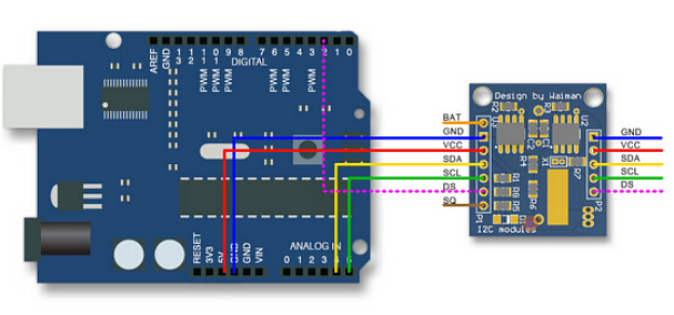
https://www.jaycar.com.au/arduino-compatible-real-time-clock-module/p/XC4450
https://cdn.hackaday.io/files/471322016495488/XC4450-manualMain.pdf
https://www.jaycar.com.au/medias/sys_master/images/images/9403724890142/XC4450-manualMain.pdf
Includes
DS1307I2C RTC
24C32 32K I2C EEPROM Storage
DS18B20 Temperature sensor
RAIN SENSOR
https://create.arduino.cc/projecthub/MisterBotBreak/how-to-use-a-rain-sensor-bcecd9
Rain Sensor | Colour | Arduino |
VCC | red | 5V |
GND | black | GND |
TTL | green | 9 |
AS | yellow | A1 |
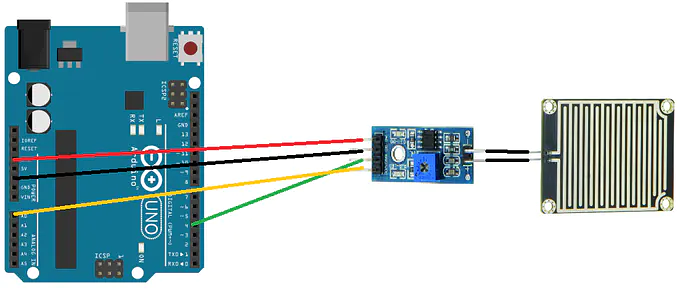
WIND SPEED SENSOR (Magnet Sensor)
https://create.arduino.cc/projecthub/achindra/diy-anemometer-wind-speed-sensor-device-84a2e3
https://core-electronics.com.au/anemometer-wind-speed-sensor-w-analog-voltage-output.html - $100, expensive but worth looking at how it works.
https://cdn-shop.adafruit.com/datasheets/US5881_rev007.pdf
higH frequency hall effect (overkill?)
https://maker.pro/arduino/tutorial/how-to-use-a-hall-effect-sensor-with-arduino
https://www.altronics.com.au/p/z6367-magnetic-44e-hall-effect-sensor-breakout/
Power consumption :
2/072020
12 SLA -> 9Vdc -> Arduino Uno -> DHT11 -> 128 x 64 LCD = 74 mA ( 1 second update )
Battery Charger
https://core-electronics.com.au/lithium-battery-charger.html
Memory optimisation
https://arduinojson.org/v5/faq/how-to-reduce-memory-usage/
Record current memory usage
Comment | % Global Vars Used | % Sketch storage space used |
Everything in (U8G2 + DHT libraries) | 79% | 69% |
No methods just libraries U8G2 + DHT | 77% | 23% |
No U8G2 library | 8% | 4% |
No U8G2 + DHT library | 8% | 4% |
Everything in but the U8G2 functions and library | 10% | 9% |
Turn off U8g2 features we don’t use
https://github.com/olikraus/u8g2/wiki/u8g2optimization
https://github.com/olikraus/u8g2/issues/713
Some people suggest using Page buffer instead of Full buffer to optimise
Comment | Global Vars Used | Sketch storage space used |
U8G2_ST7920_128X64_F_SW_SPI | 1629bytes 79% | 22258bytes 69% |
U8G2_ST7920_128X64_1_SW_SPI | 733bytes 35% | 22272bytes 69% |
Use unifont only | 733bytes 35% | 20114 bytes 62% |
basicGLCD library
Install basicGLCD through Library Manager (version 1.0.1)
Comment | % Global Vars Used | % Sketch storage space used |
Use DFRobot LCD library (LCD1286RSPI) = broken
https://wiki.dfrobot.com/3-wire_Serial_LCD_Module__Arduino_Compatible___SKU_DFR0091_
Download DFRobot Library: https://www.dfrobot.com/image/data/DFR0091/LCD12864R%20v1.0.zip
Test: File -> Examples -> LCD12864RSPI -> test
Error:
LCD12864_test:27:10: error: wiring.h: No such file or directory
#include "wiring.h"
^~~~~~~~~~
compilation terminated.
exit status 1
wiring.h: No such file or directory
Could not find boards.txt in /home/map7/sketchbook/hardware/LeoStick/bootloaders. Is it pre-1.5?
Could not find boards.txt in /home/map7/sketchbook/hardware/LeoStick/cores. Is it pre-1.5?
This hasn’t been updated since 2014 and the wiring.h has been replaced with wiring_private.h. I tried changing this in the library but as the library is too old there are a lot of other problems here.
Comment | % Global Vars Used | % Sketch storage space used |
Mounting
Mick’s Weather Station
To mount the Weather station outside I’m going to design a board which attaches to the wall and has a hinge for easy removal of the waterproof case. This will go on the brick fence which I can see from the kitchen on the inside of the west wall.
This covers mounting, cable management, sensor arrangement and LCD display all in one picture.
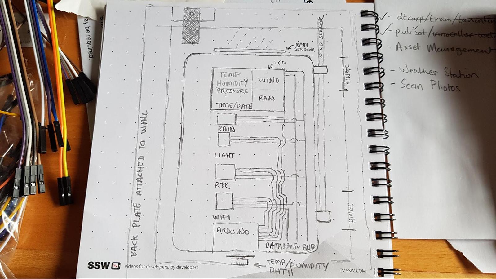
Inside readout
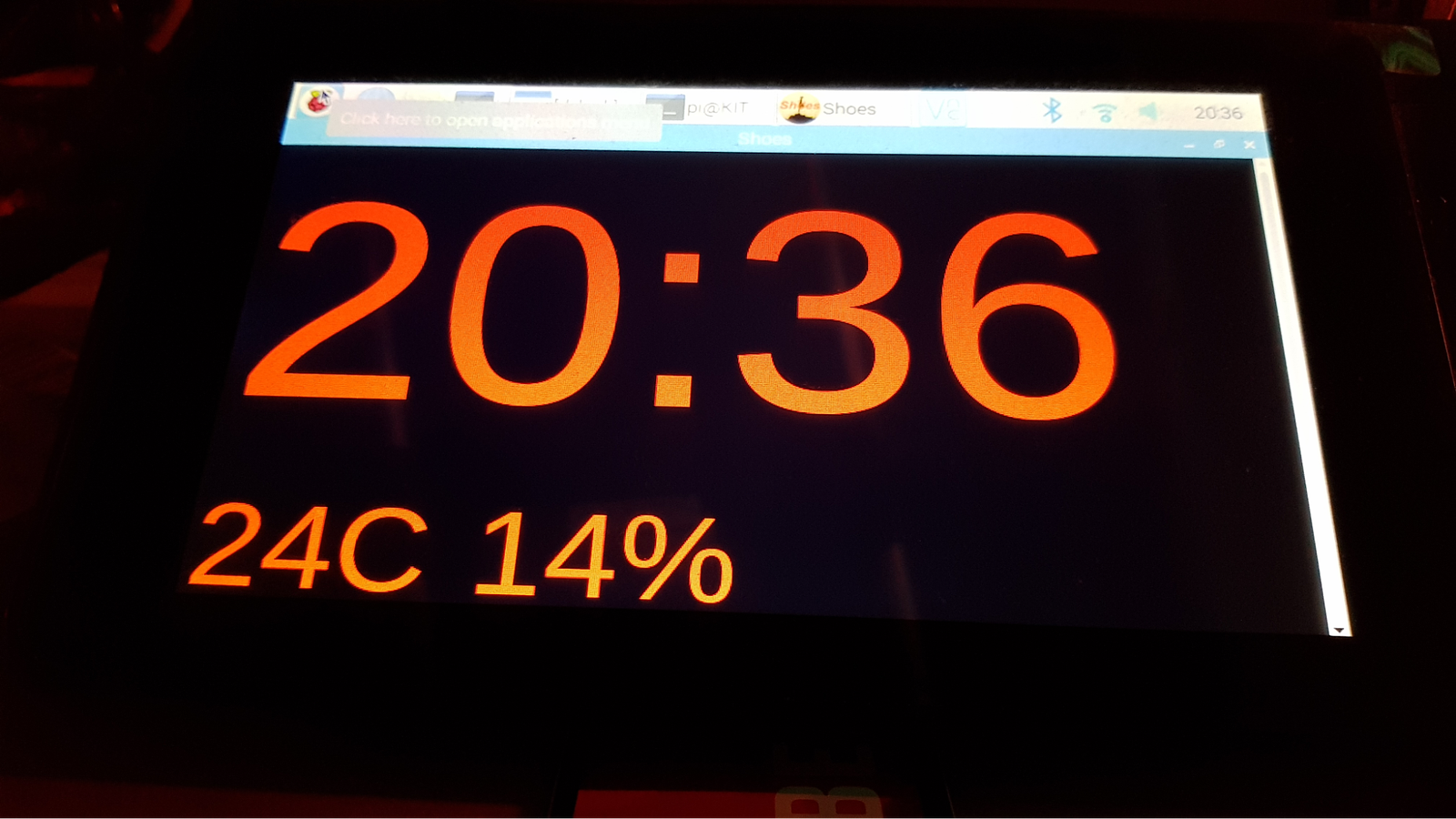
I(Mick) already have a Raspberry PI 4 with 7inch display inside for displaying the time. I noticed that we can easily get the latest readings from thingspeak.com
Using ruby I created a little GUI to display the outside readouts inside my house;
https://github.com/map7/home_dashboard
require 'net/http'
require 'json'
require 'byebug'

url = 'https://api.thingspeak.com/channels/1097373/feeds/last.json'
uri = URI(url)

Shoes.app width: 720, height: 480 do
  background "#000"
  @clock = para "00:00"
  @clock.style(:stroke => red, :font => "130")

  @temperature = para "00C "
  @temperature.style(:stroke => red, :font => "40")

  @humidity = para "00%"
  @humidity.style(:stroke => red, :font => "40")

  every 1 do
        @clock.text = Time.now.strftime("%H:%M")

        # Update Temperature & Humidity
        response = Net::HTTP.get(uri)
        response = JSON.parse(response)
        @temperature.text = response["field1"] + "C "
        @humidity.text = response["field2"] + "%"
  end
 end
This is displayed inside and I hope to add more readouts in the future. Maybe take that info and do something else with it like turn on/off Air Cons.
MILESTONES
28/06/2020: DHT11 displaying on 128x64 LCD screen
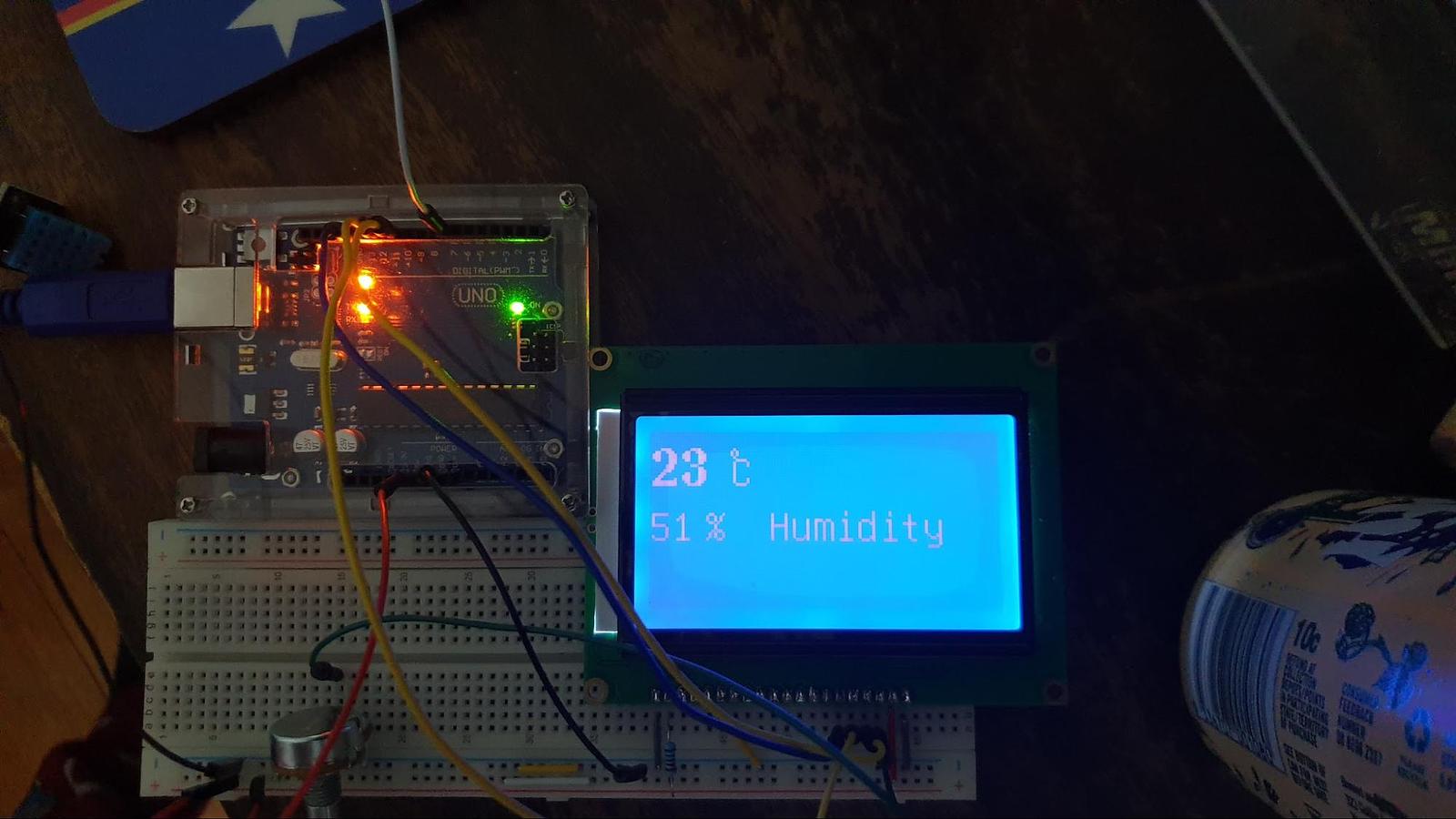
Danch’s setup
06/07/2020: RTC
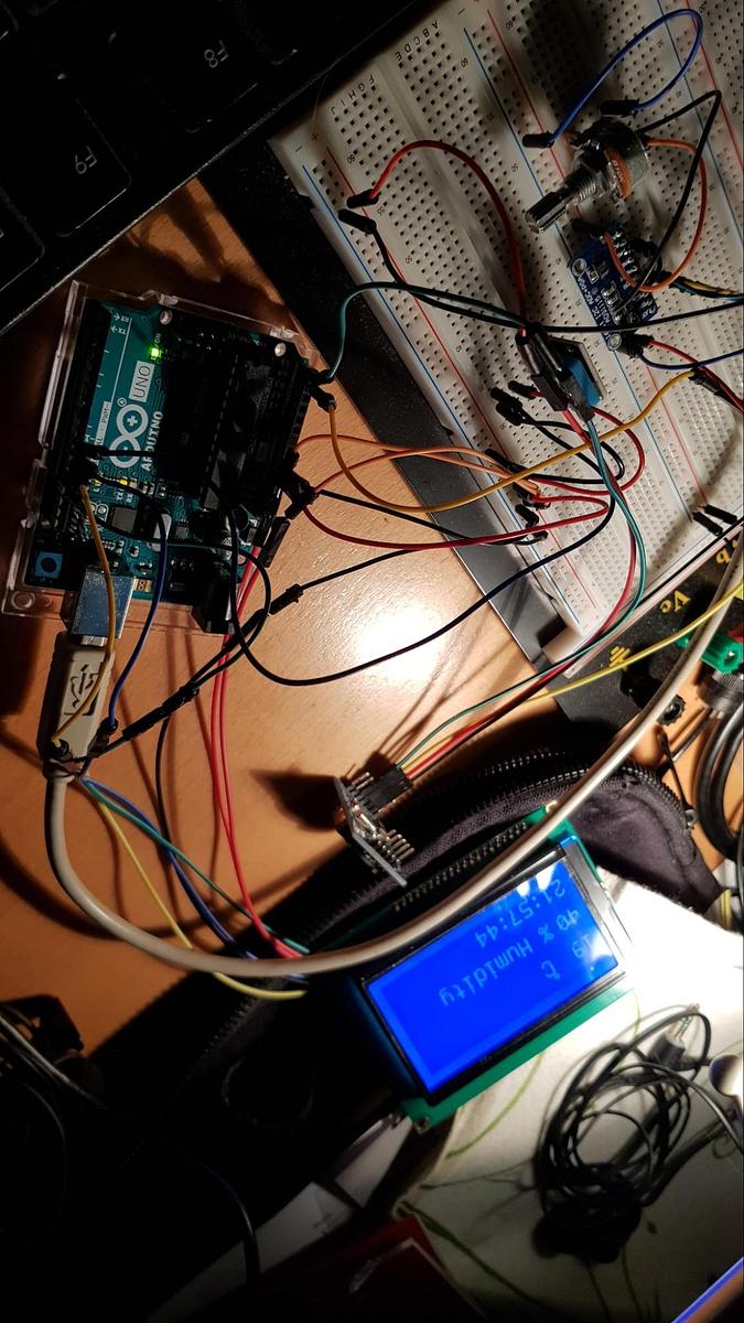
Mick’s setup
08/07/2020: WIFI ESP8266 connecting
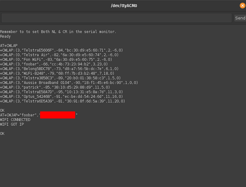
Success! We connected to our Home networks on attempt 1 : 8/7/20
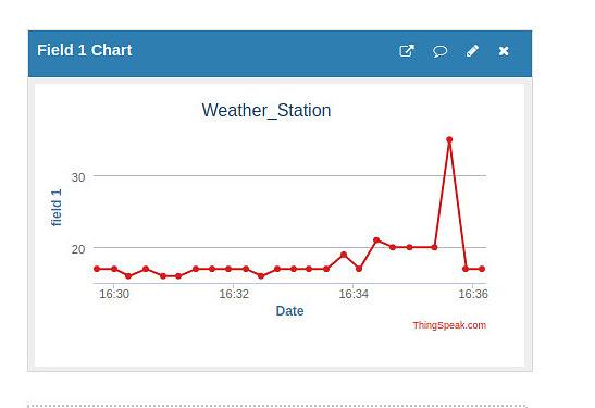
11/07/2020: Logging to ThingSpeak
Logging analog temperature data to ThingSpeak from the Arduino via the ESP8266 with AT commands every 10 seconds.
15/07/2020: LDR
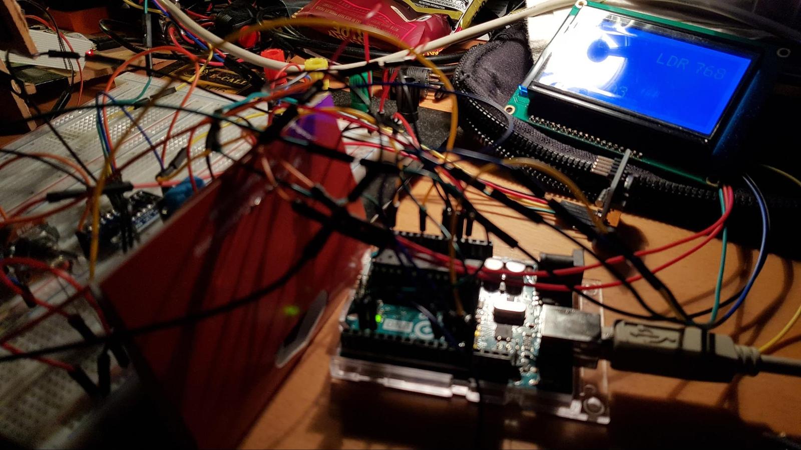
Hooked up LDR, displayed it on the LCD and sent the data to ThingSpeak.
20/07/2020: Soldering
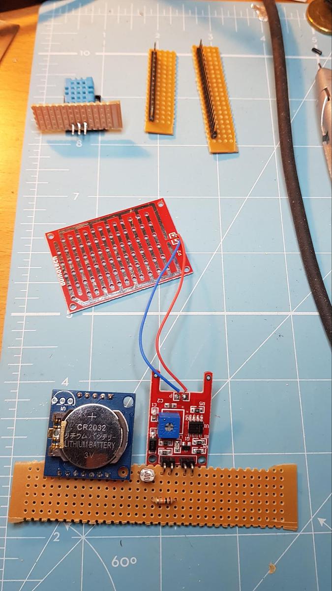
Started soldering the RTC, LDR, DHT, Rain Sensor & Some headers for the Arduino. The DHT is going outside the box which is why it’s on it’s own. The headers are on their own because the copper is on the other side and I cannot fit the components on there. The last position on the bottom board is going to be the ESP8266.
22/07/2020: Rain Sensor
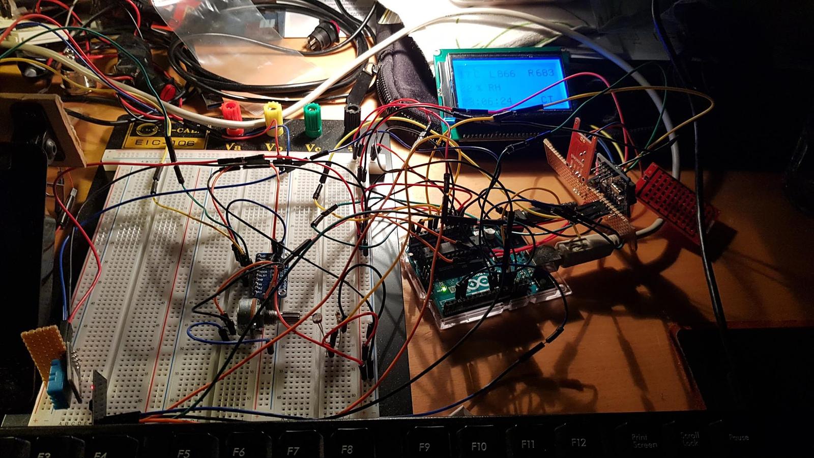
Added the Rain Sensor tonight.
30/07/2020: Soldering all internal components
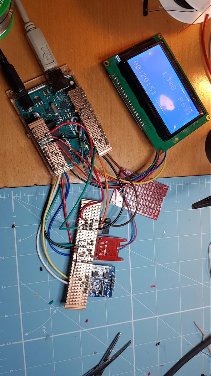
Soldered RAIN, RTC & ESP8266, all works.
02/08/2020: Mounted outside
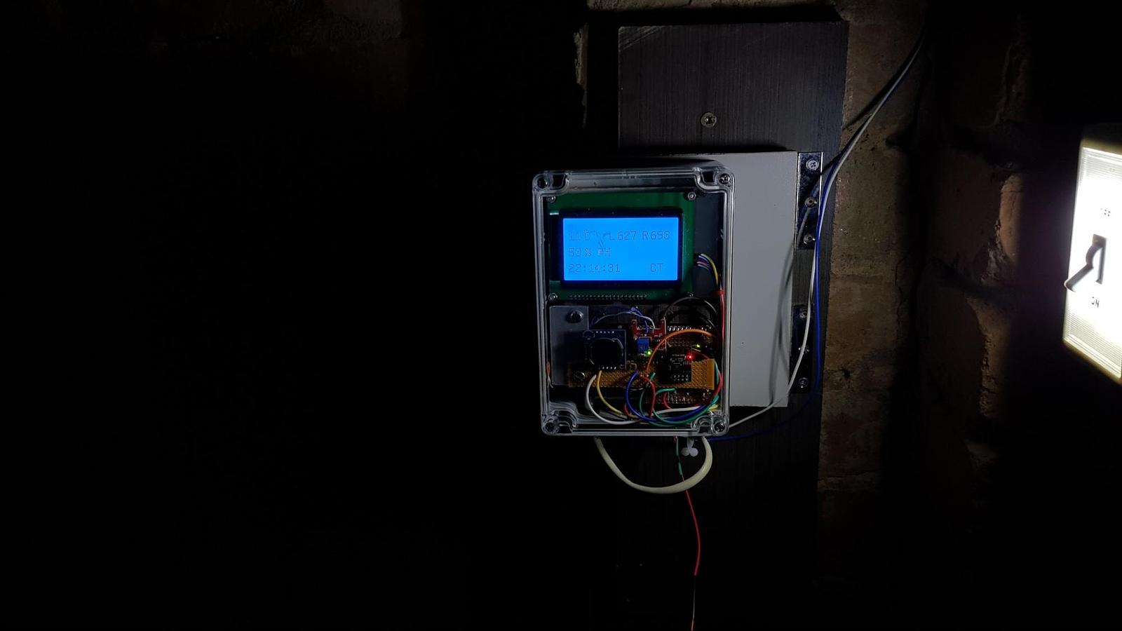
Mounted outside!
28/01/2021: Separate inside realtime readout
[a]Check this link out