Weather Station 2.0
- STARTED
- 14/11/2025
- BY
- Michael Pope and Danch
- TAGS
- hobby
- PRINTED
- 13 Oct 2026
Weather Station 2.0
Date: 14th Nov, 2025
Build of Materials
Current
ESP32 Dev Module
BME280 ( Temp, Humidity and pressure sensor)
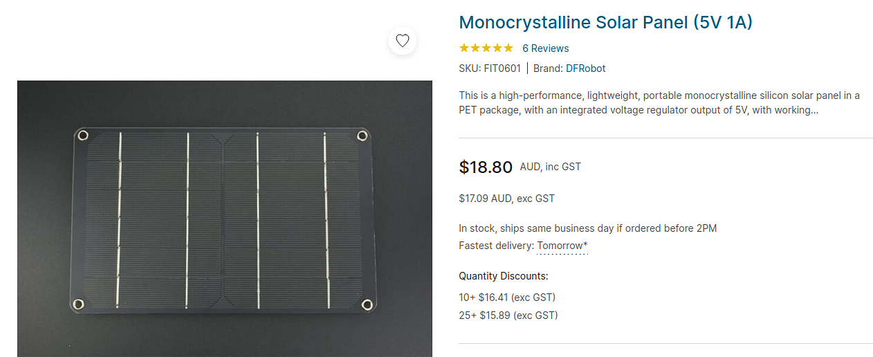
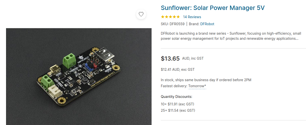
- 1 x 18650 battery and holder
- Fire Beetle 2 ESP32 C6
1 x 18650 protected battery
Future
Requirements
Record
Temperature
Humidity
Wind (speed,direction)
Lightning (SEN0290)
Rain
Pressure
Soil moisture
Over The Air (OTA) programming
Deep / Light sleep
Solar
Protected 18650s
Record over WIFI to flask/sinatra app
MQTT (maybe)
3D printing parts (Wind, Rain & Enclosure)
Setting up Fire Beetle 2 ESP32 C6
Blink Example
https://wiki.dfrobot.com/SKU_DFR1075_FireBeetle_2_Board_ESP32_C6#target_8
Had to add the repository for the boards and update all the boards through the board manager, then select the correct ‘FireBeetle 2 ESP32 C6’ board.
#define ONBOARD_LED 15 |
Sensors
BME280
Lightning Sensor
https://core-electronics.com.au/gravity-lightning-sensor.html
Pin outs of the ESP32 WROOM (ESP32 DEV MODULE)
https://randomnerdtutorials.com/esp32-pinout-reference-gpios/
https://circuits4you.com/2018/12/31/esp32-devkit-esp32-wroom-gpio-pinout/
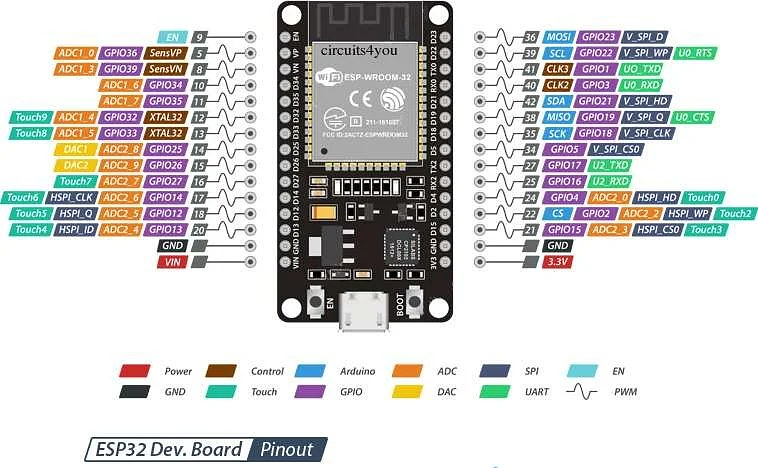
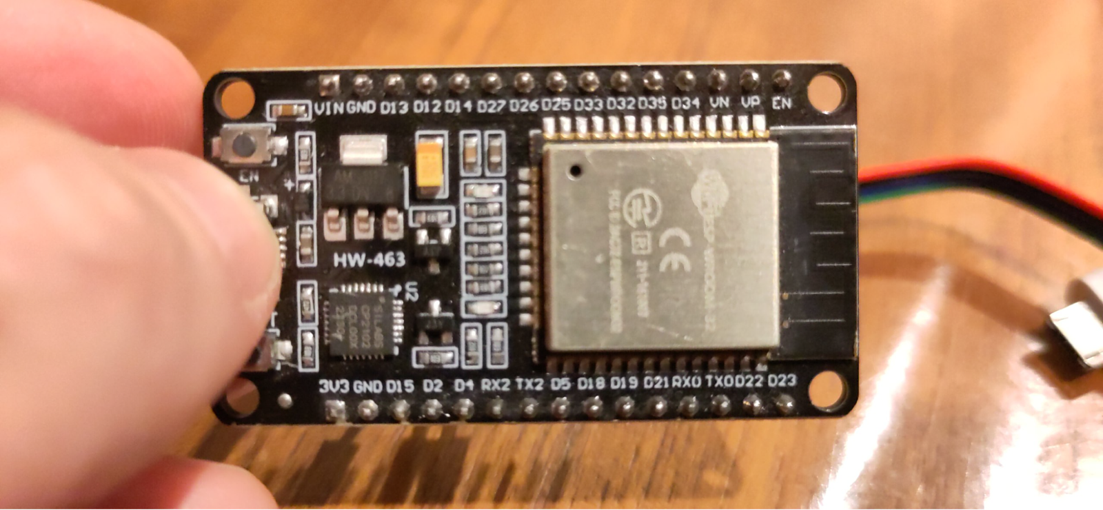
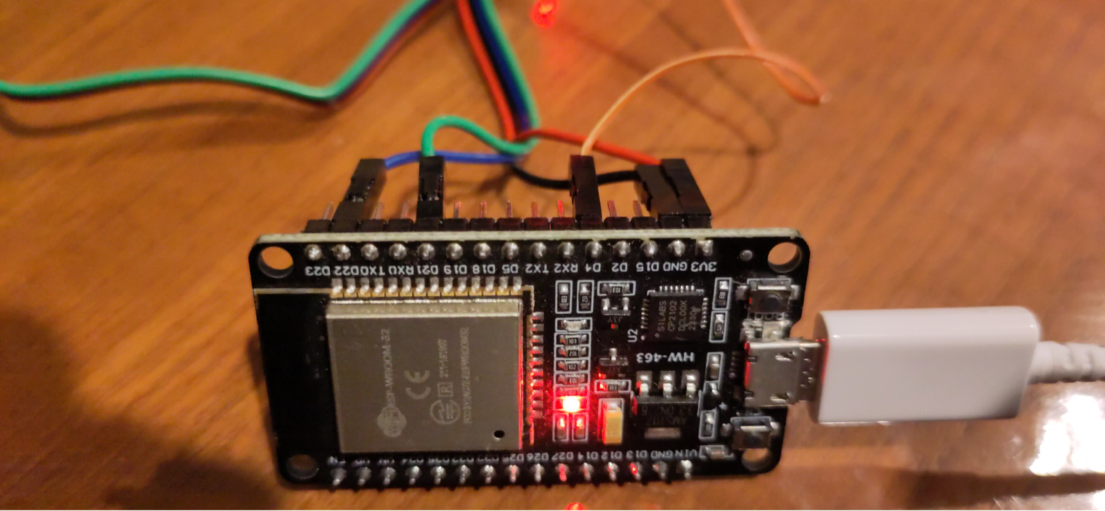
Lightning Sensor | Wire Colour | Arduino |
VCC | red | 3.3V |
GND | black | GND |
SCL | blue | SCL GPIO22 |
SDA | green | SDA GPIO21 |
IRQ (Interupt) | orange | GPIO4 |
Setup
https://wiki.dfrobot.com/Gravity%3A%20Lightning%20Sensor%20SKU%3A%20SEN0290#More_Documents
Download the DF library -> Go to github and Download ZIP
Unzip into ~/Arduino/libraries
Open Arudino IDE
Go to File -> Examples -> DFRobotAS3935 -> Detailed
Change the following
#define IRQ_PIN 0
TO
#define IRQ_PIN 4
Mick Ref: ~/Arduino/esp32_lightning
Publish on MQTT
NOTE: Most of the MQTT documentation is in our Modbus Google Doc
Version 1
/*!
 * @file DFRobot_AS3935_lightning_sensor_detailed.ino
 * @brief SEN0290 Lightning Sensor
 * @n This sensor can detect lightning and display the distance and intensity of the lightning within 40 km
 * @n It can be set as indoor or outdoor mode.
 * @n The module has three I2C, these addresses are:
 * @n  AS3935_ADD1  0x01   A0 = 1  A1 = 0
 * @n  AS3935_ADD2  0x02   A0 = 0  A1 = 1
 * @n  AS3935_ADD3  0x03   A0 = 1  A1 = 1
 * @copyright   Copyright (c) 2010 DFRobot Co.Ltd (http://www.dfrobot.com)
 * @license     The MIT License (MIT)
 * @author [TangJie](jie.tang@dfrobot.com)
 * @version  V1.0.2
 * @date  2019-09-28
 * @url https://github.com/DFRobot/DFRobot_AS3935
 */


#include "DFRobot_AS3935_I2C.h"
#include <WiFi.h>
#include <PubSubClient.h>

// WIFI Setup
const char* ssid = "foobar";
const char* password = "skylineoscarjava";

WiFiClient espClient;

// MQTT Setup
const char* mqtt_server = "10.1.1.11";
PubSubClient client(espClient);
unsigned long lastMsg = 0;
#define MSG_BUFFER_SIZE (50)
char msg[MSG_BUFFER_SIZE];
int value = 0;

// Lightning Setup
volatile int8_t AS3935IsrTrig = 0;

#if defined(ESP32) || defined(ESP8266)
#define IRQ_PIN       4
#else
#define IRQ_PIN       2
#endif

// Antenna tuning capcitance (must be integer multiple of 8, 8 - 120 pf)
#define AS3935_CAPACITANCE   96

// I2C address
#define AS3935_I2C_ADDR       AS3935_ADD3

void AS3935_ISR();

DFRobot_AS3935_I2C  lightning0((uint8_t)IRQ_PIN);

void setup()
{

  Serial.begin(115200);
  setup_wifi();

  Serial.println("Setup MQTT Server");
  client.setServer(mqtt_server, 1883);
  client.setCallback(callback);

  Serial.println("DFRobot AS3935 lightning sensor begin!");

  lightning0.setI2CAddress(AS3935_ADD3);

  while (lightning0.begin() != 0){
    Serial.print(".");
  }
  lightning0.defInit();

  // Configure sensor
  lightning0.powerUp();

  //set indoors or outdoors models
  lightning0.setIndoors();
  //lightning0.setOutdoors();

  //disturber detection
  lightning0.disturberEn();
  //lightning0.disturberDis();

  lightning0.setIRQOutputSource(0);

  #if defined(ESP32) || defined(ESP8266)
  attachInterrupt(digitalPinToInterrupt(IRQ_PIN),AS3935_ISR,RISING);
  #else
  attachInterrupt(/*Interrupt No*/0,AS3935_ISR,RISING);
  #endif
  delay(500);
  //set capacitance
  lightning0.setTuningCaps(AS3935_CAPACITANCE);
  Serial.println("AS3935 manual cal complete");

// Enable interrupt (connect IRQ pin IRQ_PIN: 2, default)
//  Connect the IRQ and GND pin to the oscilloscope.
//  uncomment the following sentences to fine tune the antenna for better performance.
//  This will dispaly the antenna's resonance frequency/16 on IRQ pin (The resonance frequency will be divided by 16 on this pin)
//  Tuning AS3935_CAPACITANCE to make the frequency within 500/16 kHz ± 3.5%
//  lightning0.setLcoFdiv(0);
//  lightning0.setIRQOutputSource(3);

// Set the noise level,more than 7 will use the default value:2
  lightning0.setNoiseFloorLvl(2);
  //uint8_t noiseLv = lightning0.getNoiseFloorLvl();

//used to modify WDTH,alues should only be between 0x00 and 0x0F (0 and 7)
  lightning0.setWatchdogThreshold(2);
  //uint8_t wtdgThreshold = lightning0.getWatchdogThreshold();

  //used to modify SREJ (spike rejection),values should only be between 0x00 and 0x0F (0 and 7)
  lightning0.setSpikeRejection(2);
  //uint8_t spikeRejection = lightning0.getSpikeRejection();
}

void setup_wifi() {


 delay(10);
 // We start by connecting to a WiFi network
 Serial.println("Connecting to ");
 Serial.println(ssid);

 WiFi.mode(WIFI_STA);
 WiFi.begin(ssid, password);

 while (WiFi.status() != WL_CONNECTED) {
   delay(500);
   Serial.print(".");
 }

 randomSeed(micros());

 Serial.println("\nWiFi connected");
 Serial.println("IP address: ");
 Serial.println(WiFi.localIP());
}

void reconnect_wifi() {
 // Loop until we're reconnected
 while (!client.connected()) {
   Serial.print("Attempting MQTT connection...");

   // Create a random client ID
   String clientId = "ESP8266Client-";
   clientId += String(random(0xffff), HEX);

   // Attempt to connect
   if (client.connect(clientId.c_str())) {
     Serial.println("connected");

   } else {
     Serial.print("failed, rc=");
     Serial.print(client.state());
     Serial.println(" try again in 5 seconds");

     // Wait 5 seconds before retrying
     delay(5000);
   }
 }
}

void callback(char* topic, byte* payload, unsigned int length) {
 Serial.print("Message arrived [");
 Serial.print(topic);
 Serial.print("] ");
 for (int i = 0; i < length; i++) {
   Serial.print((char)payload[i]);
 }
 Serial.println();
}

void loop()
{

  // WIFI
  if (!client.connected()) {
    reconnect_wifi();
   }
   client.loop();

  // It does nothing until an interrupt is detected on the IRQ pin.
  while (AS3935IsrTrig == 0) {delay(1);}
  delay(5);

  // Reset interrupt flag
  AS3935IsrTrig = 0;

  // Get interrupt source
  uint8_t intSrc = lightning0.getInterruptSrc();
  if (intSrc == 1){
    // Get rid of non-distance data
    uint8_t lightningDistKm = lightning0.getLightningDistKm();
    Serial.println("Lightning occurs!");
    Serial.print("Distance: ");
    Serial.print(lightningDistKm);
    Serial.println(" km");

    // Get lightning energy intensity
    uint32_t lightningEnergyVal = lightning0.getStrikeEnergyRaw();
    Serial.print("Intensity: ");
    Serial.print(lightningEnergyVal);
    Serial.println("");

    snprintf (msg, MSG_BUFFER_SIZE, "Lightning! Distance: #%ld km", lightningDistKm);


  }else if (intSrc == 2){
    Serial.println("Disturber discovered!");
    snprintf (msg, MSG_BUFFER_SIZE, "Disturber discovered!");
  }else if (intSrc == 3){
    Serial.println("Noise level too high!");
    snprintf (msg, MSG_BUFFER_SIZE, "Noise level too high!");
  }
  //View register data
  //lightning0.printAllRegs();

 // Publish data to MQTT
 unsigned long now = millis();
 if (now - lastMsg > 2000) {
   lastMsg = now;
   ++value;

   //snprintf (msg, MSG_BUFFER_SIZE, "hello world #%ld", value);
   Serial.print("Publish message: ");
   Serial.println(msg);

   client.publish("/weather/lightning", msg);
 }

}

//IRQ handler for AS3935 interrupts
#if defined(ESP32) || defined(ESP8266)
void IRAM_ATTR AS3935_ISR()
#else
void AS3935_ISR()
#endif
{
  AS3935IsrTrig = 1;
}
Version 2
/*! |
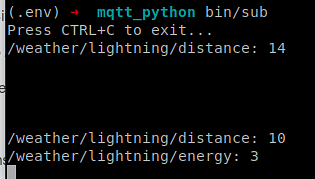
Output MQTT Version 2
/home/ava/code/mqtt_python/bin/sub contents;
#!/usr/bin/env bash |
NOTE: Using absolute paths
Mick setup
$ ssh ava
$ cd ~/code/mqtt_python
$ bin/sub
Create a startup script
Create /etc/systemd/system/lightning.service
[Unit] |
Load the service
$ systemctl daemon-reload
$ systemctl enable lightning.service
$ systemctl start lightning.service
Test the screen service is working
$ su ava
$ screen -r lightning
NOTE: You should see the heartbeat dots.
Test in Garage
When I (Mick) tested the esp32 + lightning sensor with Version 2 of the code 17/07/2025 it didn’t want to play the game. It would work when connected to my notebook on the USB 2.0 (right side), but not when I plugged the esp32 into the mains USB port.
I also tried plugging it into the PI1 USB2.0 and I connected to it via the PI through screen
$ screen /dev/ttyUSB0 115200
But it was reconnecting over and over, no go.
So I think it’s very picky about the USB we put it on.
Issues
Funny Characters
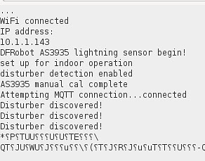
I think this was due to using a USB 3 port instead of a USB 2 port. On my Lenovo P14s the left is USB 3.0 and the right is USB 2.0.
I2C NACK Error
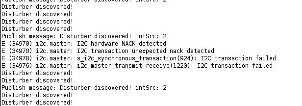
Upgrade to Arduino AVR Boards 1.8.6 instead of 1.8.3 through the Tools -> Boards -> Board Manager. = fail
Downgrade esp32 to 3.1.3
Setup Sinatra Server
Setup API
SQLite
Views
Graphs
Setup Light Sleep
Setup OTA
Setup Solar
Refer Danch setup
Mick: Could use my old solar panel from Bike.
Setup Enclosure
Future
ESP32 Tasks - https://www.youtube.com/watch?si=aK--ANueKvdR4YVx&v=382p1NT1Wcs&feature=youtu.be
ESP32 Watch
https://core-electronics.com.au/esp32-s3-development-board-128inch-round-touch-lcd.html
Gallery